Dimensions
R3Survey provides commands for placing bearing and distance dimensions on survey plan segments, configuring dimension settings, flipping labels, dimensioning Reference Marks, and managing paper space text.
Annotative text not supported
R3Survey does not support annotative text styles. Text height is scaled manually using the drawing scale set by R3DWGSCALE. If your current text style is annotative, R3DIMS, R3ADDRMLABELS, and R3ADDPMLABELS will warn you and stop. Switch to a non-annotative text style before running these commands. Future versions may add annotative text support.
R3DIMSSETTINGS — Dimension settings
Command: R3DIMSSETTINGS
Opens the Label Settings dialog where you configure how R3Survey places dimension labels, reference mark labels, permanent mark labels, plan text, and titleblock settings. Settings are saved per-user and persist across drawings.
The dialog has five tabs:
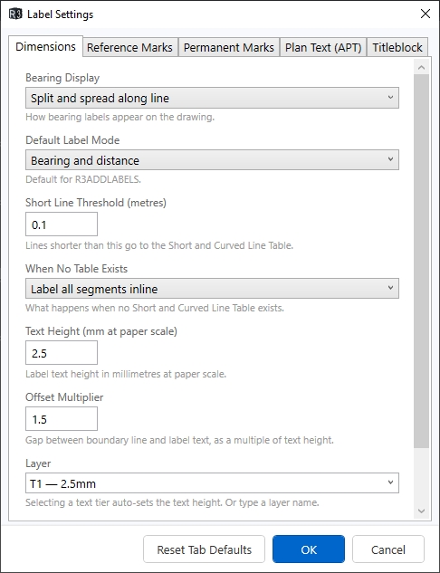
Dimensions tab
Controls how R3DIMS places bearing and distance labels on survey plan segments.
| Setting | Description | Default |
|---|---|---|
| Bearing Display | How bearing labels appear: Split and spread (separate deg/min/sec entities spread along the line), Single with spaces, or Single compact | Split and spread |
| Default Label Mode | Bearing and distance places both; Distance only omits bearings from inline labels and the text table | Bearing and distance |
| Short Line Threshold | Lines shorter than this (in metres) are routed to the Short & Curved Line Table instead of inline labels | 8.0 |
| When No Table Exists | What happens when the drawing has no Short & Curved Line Table: Create text table (rows without borders), Label all inline, or Skip and warn | Create text table |
| Table Style Name | The AutoCAD table style name to search for | Short & Curved Line Table |
| Text Height | Label text height in millimetres at paper scale. The drawing scale (from R3DWGSCALE) is applied automatically |
2.5 |
| Offset Multiplier | Gap between the boundary line and label text, as a multiple of text height | 1.5 |
| Layer | The text tier used for plan entities (T0–T4). When selected entities are on a survey plan layer, R3DIMS uses this tier from that plan. When selected entities are not on any plan, the current active layer is used. You can also type a custom layer name | T1 |
| Group Collinear Bearings | When checked, consecutive polyline legs with the same bearing are grouped under a single bearing label | On |
Reference Marks tab
Controls how R3ADDRMLABELS places reference mark labels.
| Setting | Description | Default |
|---|---|---|
| Default Label Mode | Text places MText at each RM. Table adds rows to the RM schedule table | Text |
| When No Table Exists | What happens when Table mode is selected but no RM schedule table exists: Create text table or Label all inline | Create text table |
| Text Height | RM label text height in millimetres at paper scale | 2.5 |
| Label Format | Numbering style: Numeric (1, 2, 3...) or Alpha (A, B, C...) | Numeric |
| Label Prefix | Text prepended to each label (e.g. RM → RM1, RM2). Leave empty for plain numbers/letters |
— |
| Layer | Text tier (T0–T4), active layer, or custom layer name. Selecting a tier auto-sets the text height | T1 |
Permanent Marks tab
Controls how R3ADDPMLABELS places mark labels, designations, and connection dimensions. This tab has three sections:
Mark Labels — text placed next to each PM block (e.g. SS 62274 FD):
| Setting | Description | Default |
|---|---|---|
| Mark Label Text Height | Text height in mm at paper scale | 3.5 |
| Mark Label Layer | Text tier, active layer, or custom layer name | T2 |
Designations — letter placed next to each PM (e.g. X, Y) identifying the mark in coordinate connections:
| Setting | Description | Default |
|---|---|---|
| Designation Style | Letter sequence: X, Y, Z or A, B, C | X, Y, Z |
| Designation Text Height | Text height in mm at paper scale | 3.5 |
| Designation Layer | Text tier, active layer, or custom layer name | T2 |
Connection Dimensions — bearing/distance text along control lines:
| Setting | Description | Default |
|---|---|---|
| Connection Dimensions Mode | Text along lines places BY SURVEY + MGA GROUND labels. Table adds rows to the R3_COORD_CONNECTIONS table | Text along lines |
| When No Table Exists | What happens when Table mode is selected but no table exists: Create text table or Place text along lines instead | Create text table |
| Connection Text Height | Text height in mm at paper scale | 2.5 |
| Connection Text Layer | Text tier, active layer, or custom layer name | T1 |
Plan Text (APT) tab
Maps parcel classes to text tiers for automatic plan text placement. Each parcel class can use a different text tier (T0–T4), which determines the layer and text height.
| Parcel Class | Includes | Default |
|---|---|---|
| Roads | Road, Reserved Road, Railway | T3 (5.0mm) |
| Easements | Easement, Covenant, Positive Covenant, RUOL, ROU, Profit A Prende | T1 (2.5mm) |
| Hydrography | Water bodies | T3 (5.0mm) |
| Administrative Areas | LGA, parish, county | T2 (3.5mm) |
| Lots | UseOfParcel text | T2 (3.5mm) |
| Miscellaneous | Building, Common Property, Lease, etc. | T1 (2.5mm) |
Titleblock tab
Controls the layer used when inserting titleblock and north point blocks (R3INSERTPF1, R3INSERTPF2, R3NORTH).
| Setting | Description | Default |
|---|---|---|
| Titleblock Layer | Text tier (T0–T4), active layer, or custom layer name | Active layer |
Tip
Access Label Settings from the R3Survey menu: R3Survey > Dimensions > Dim Settings...
R3DIMS — Auto-dimension survey plan segments
Command: R3DIMS
Units requirement
R3DIMS currently requires angle units set to DMS (north azimuths) and length units set to Metres. Other formats (surveyor's bearings, gons, feet) are not yet supported. The command will warn you and stop if different units are detected. Set units with R3UNITS or R3SETTINGS.
Automatically places bearing and distance labels on selected survey plan segments. Short lines and arcs are routed to a Short & Curved Line Table; longer straight lines get inline bearing and distance text placed midway along the leg.
R3DIMS works in both model space and paper space layouts — it detects the current context automatically.
Usage — Model tab
- Type
R3DIMSfrom the Model tab - Select the segments to dimension (window, crossing, or individual picks)
- Press Enter to finish selection
R3Survey routes each selected segment:
| Segment type | Result |
|---|---|
| Arc | Routed to the Short & Curved Line Table + numbered circle marker placed at midpoint |
| Line shorter than threshold | Routed to the Short & Curved Line Table + numbered circle marker |
| Line longer than threshold | Inline bearing + distance label placed at midpoint |
Usage — Layout tab (paper space)
Double-click inside a viewport to enter floating model space, then type R3DIMS. The workflow is the same, but labels and markers are placed in paper space at the correct paper size rather than in model space.
Text orientation
Labels are oriented so they are readable from the bottom or right side of the current view. If you are working in a rotated UCS view (e.g. using PLAN to align a boundary horizontally), R3DIMS accounts for the view twist so text reads correctly in the rotated view.
A 10-degree bias is applied at the vertical boundary: lines within 10 degrees of north always have text pointing upward (readable from the east side), matching NSW survey plan convention.
Text table fallback
When no Short & Curved Line Table exists in the drawing, short lines and arcs are handled according to the When No Table Exists setting in R3DIMSSETTINGS:
- Create text table — prompts for a starting number and insertion point, then writes dimension data as text rows (without borders). Column headings are NO., BEARING, DISTANCE, ARC, RADIUS. In Distance only mode the BEARING column is omitted.
- Label all inline — places all segments as inline labels regardless of length.
- Skip and warn — skips short/arc segments and warns.
The text table is oriented to the current view, so it reads correctly even in a rotated UCS.
Layer placement
R3DIMS determines where to place dimension labels based on what you select:
| Selection | Label layer |
|---|---|
| All entities on a single survey plan | That plan's text tier layer (configured in Label Settings) |
| All entities not on any survey plan | The current active layer |
| Mixed selection (multiple plans, or plan + non-plan) | Command stops with a warning — select entities from one plan at a time |
This means you do not need to set a working plan to use R3DIMS. If you select boundaries from a survey plan, the dimensions go to that plan's text tier automatically. If you select standalone geometry (lines, polylines not on a plan layer), dimensions go to whatever layer is current.
Segment selection tips
- Window or crossing — select multiple segments at once
- Ctrl+click on a polyline — selects a single polyline segment rather than the whole polyline
- Coincident segments shared between adjacent lots are automatically deduplicated
Collinear grouping
When consecutive legs of a polyline share the same legal bearing and are connected end-to-end, R3DIMS groups them and places a single bearing label spanning the full chain. Each leg still receives its own distance label.
Short & Curved Line Table
R3DIMS appends to an existing table — it does not create the table itself. The table must be an AutoCAD TABLE entity with the style name configured in R3DIMSSETTINGS (default: Short & Curved Line Table) already placed in the drawing.
Each run appends new rows starting from the next available row number. Re-running R3DIMS on segments already in the table will add duplicate entries — select only new segments each time.
Multi-page plans
Survey plans that span multiple pages (e.g. a large subdivision with Sheet 1 and Sheet 2 showing different areas) benefit from placing dimensions in paper space rather than model space.
Why paper space? When dimensions are in model space, every viewport that shows the same area displays the same text. For multi-page plans with overlapping coverage, this means text intended for Sheet 1 also appears on Sheet 2 — and you'd need per-viewport layer freezes (VP Freeze) to hide it selectively. This is tedious and error-prone.
Paper space annotation avoids this entirely. Text placed in paper space only exists on the sheet where you placed it. There are no conflicts between sheets, even when viewports overlap.
Workflow:
- Set up each sheet as a separate layout with its own viewport(s)
- On each layout, double-click inside the viewport to enter floating model space
- Run
R3DIMSand select the segments to dimension for that sheet - Labels are placed in paper space at the correct paper size — they belong to that layout only
- Repeat for each sheet
Where two sheets cover overlapping areas, you choose which dimensions appear on which sheet. If a boundary appears on both sheets, you can dimension it on both (each sheet should be independently readable) or on just one — the choice is yours, with no layer management needed.
This also works for enlarged diagrams at a different scale. Each viewport can have its own R3DIMS pass — text is sized correctly for that viewport's scale and placed independently in paper space.
Tip
Use R3FLIP in paper space to move text to the other side of a boundary after placing. Use R3REPOSTEXT to adjust text positions if you change a viewport's scale after dimensioning.
R3ADDLABELS — Add bearing/distance labels to a survey plan
Command: R3ADDLABELS
Places bearing and distance labels on all segments of a survey plan. Unlike R3DIMS which works on selected segments, R3ADDLABELS labels an entire plan at once and writes XData linking each label to its source segment for automatic repositioning when geometry changes.
Usage
- Type
R3ADDLABELS - Pick any entity belonging to the survey plan
- Choose label mode: Bearing and distance or Distances only
Labels are placed on the plan's Text component layer. Segments already labelled (with existing R3Label XData) are skipped.
R3FLIP — Flip text to the opposite side of a line
Command: R3FLIP
Reflects one or more text entities across a reference line, moving them to the opposite side. Works on any TEXT — bearing labels, distance labels, or any other text placed alongside a boundary leg. Use this when text has been placed on the wrong side.
Usage — Model space
- Type
R3FLIP - Select the text entities to flip
- Select the reference line, or Ctrl-click to select a single polyline segment
Usage — Paper space (layout tab)
- Type
R3FLIPwhile in paper space (not inside a viewport) - Select the text entities to flip
- Click two points along the visible reference line in paper space
Note
R3FLIP works on TEXT entities (not MText). Arcs are not supported as reference entities — use a line or polyline segment.
R3ADDRMLABELS — Label Reference Mark entities
Command: R3ADDRMLABELS
Places labels on all Reference Mark entities in a survey plan. Supports two output modes:
- Text — MTEXT labels showing monument data, bearing/distance observations
- Table — RM schedule table with columns: No., Bearing, Distance, Description, Source
Double RMs at the same corner with the same bearing are grouped into a single label/row showing both distances.
Usage
- Type
R3ADDRMLABELS - Pick any entity belonging to the survey plan
- Choose mode: Text or tAble
Labels are placed on the plan's Text component layer (configured in R3PLANLAYERSETTINGS).
R3REPOSTEXT — Reposition paper space text
Command: R3REPOSTEXT
Repositions the position of selected text, MText, leaders, and multileaders in paper space after a viewport scale change, without altering text height or content. Uses the same reference-distance method as AutoCAD's SCALE Reference option.
Must be run from a layout tab in paper space (not inside a viewport).
Usage
- Type
R3REPOSTEXT - Select the text/leader entities to reposition
- Pick a base point
- Pick a point at the original reference distance from the base
- Pick the corresponding point at the new reference distance
R3Survey calculates the scale ratio between the two distances and moves each entity's insertion point by that ratio around the base point. Text height, leader arrow sizes, and MText width are preserved.
R3OFFSETDIM — Offset / clearance dimension
Command: R3OFFSETDIM
Places a clearance or offset dimension in paper space between two model space points. Useful for showing the distance between a fence line and a boundary, or any other offset measurement that does not follow a boundary leg.
Must be run from floating model space (double-click into a viewport on a layout tab).
Usage
- Double-click inside a viewport to enter floating model space
- Type
R3OFFSETDIM - Click the first point of the measurement
- Click the second point
R3Survey calculates the real model-space distance between the two points, rounds it to the nearest centimetre, and places the value as text in paper space at the midpoint, aligned parallel to the picked line.
Note
1 drawing unit = 1 metre is assumed. The label is placed in paper space at the current viewport scale.
R3MOVETEXTTOLAYOUT — Move model space text to paper space
Command: R3MOVETEXTTOLAYOUT
Moves selected text, MText, leaders, and multileaders from model space into the active layout's paper space, positioned and scaled so they appear visually identical through the current viewport.
Must be run from floating model space (double-click into a viewport on a layout tab).
Usage
- Double-click inside a viewport to enter floating model space
- Type
R3MOVETEXTTOLAYOUT - Select the text/leader entities to move
- Press Enter
The selected entities are cloned into paper space at the equivalent paper position and size, then erased from model space.
Note
This command is useful when labels were placed in model space during drafting and need to be moved to paper space for final layout. After moving, the labels are independent of the viewport — changes to the viewport scale or position will not affect them.
See also
- R3DWGSCALE — set the drawing scale (controls R3DIMS text size)
- Survey Plan Layer Commands — configure plan components and layers
- R3TRAV — traverse entry
- R3PROPERTIES — view bearing and distance properties